
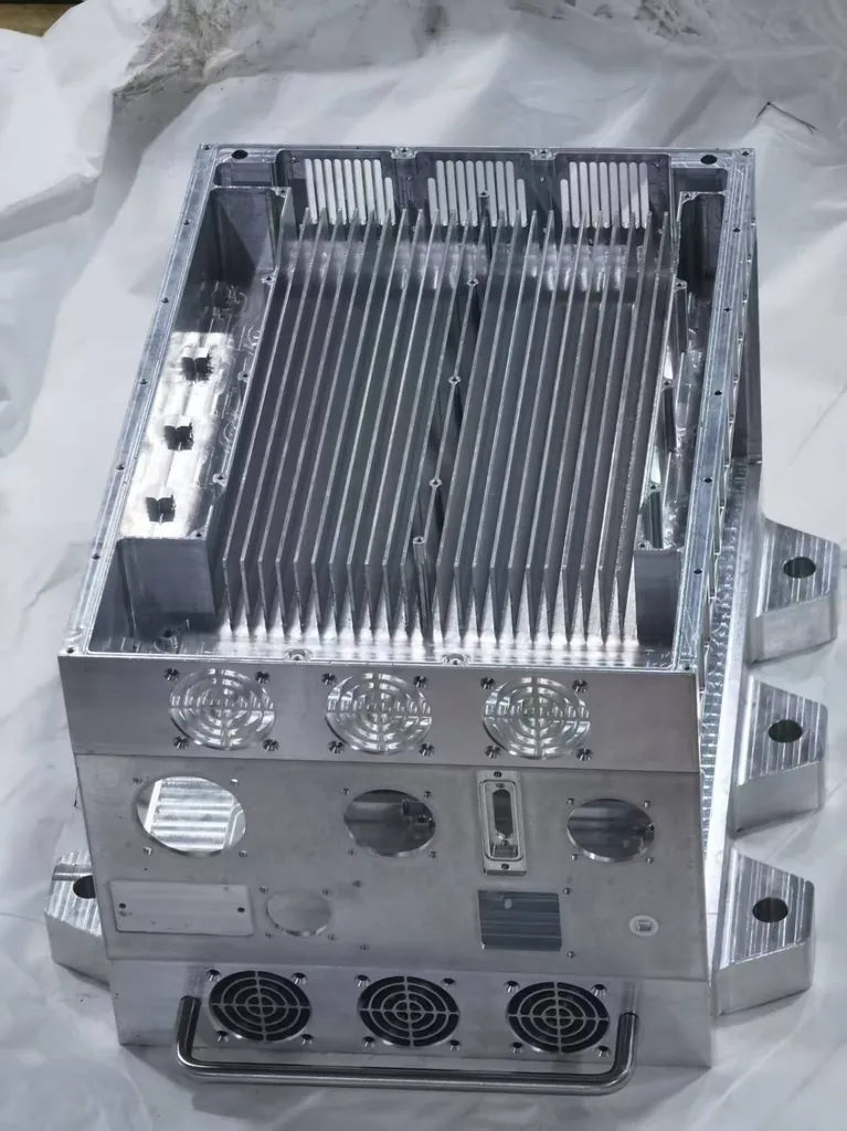
Tolerance is the number that decides whether a part works — and how much it costs. The same part marked ±0.05 mm and marked ±0.005 mm can differ by two or three times in price, even though the geometry is identical.
This guide explains what ±0.005 mm actually covers on a CNC mill and a CNC lathe, where standard tolerances are good enough, and how to write tolerances on a drawing so every supplier quotes the same thing you intended.
What a tolerance really controls
A tolerance is the allowed range for a dimension. A shaft dimension of Ø20.00 ±0.01 mm can be 19.99 or 20.01 mm. The tolerance says nothing about how round, straight or well-positioned that diameter is — those are separate geometric controls.
It also says nothing about the surface. A part can sit inside ±0.005 mm and still have a torn finish that fails inspection. Dimension, geometry and surface finish are three different conversations, and all three show up on the quote.
The tolerance ranges we work to
On our 3-axis and 4-axis machining centers we hold ±0.005 mm on critical milled features; on the CNC lathes we hold ±0.01 mm on diameters. Those are the tight ends of the range, not the default. The table below shows what is practical for common features — and what changes when a general job becomes a precision job.
| Feature | General machining | Precision (tightest) | What sets the limit |
|---|---|---|---|
| Milled profile and pocket walls | ±0.05 mm | ±0.005 mm | Tool deflection, wall height |
| Milled hole diameter | ±0.05 mm | ±0.01 mm | End mill vs. reamer |
| Hole position | ±0.1 mm | ±0.01 mm | Fixture and machine repeatability |
| Turned diameter | ±0.05 mm | ±0.01 mm | Thermal growth, tool wear |
| Turned length | ±0.1 mm | ±0.025 mm | Setup and stop position |
| Flatness / parallelism | 0.02 mm | 0.005 mm | Material stress, clamping |
| Surface finish (Ra) | 1.6 µm | 0.8 µm | Feed rate, tool, material |
Why tighter tolerance costs more
A tighter tolerance is not a machine setting; it is a different process. Four things drive the extra cost:
- More setups and more checking. A ±0.005 mm feature usually means a dedicated setup, a test cut and in-process measurement. That time is in the quote.
- Slower cutting. To hold a tight diameter you take lighter passes and leave material for a finish pass, which adds cycle time.
- Scrap risk. When the window is 10 µm wide, a worn tool or a warm machine can push a part outside it. The supplier prices that risk.
- Inspection time. Tight tolerances need measurement, not a visual check — micrometers, height gauges or a vision system, with a record for each part.
That is why the useful question is not “how tight can you machine?” but “which features actually matter?”
GD&T changes the price more than a ± does
Geometric dimensioning and tolerancing (GD&T) describes relationships between features: how flat a face must be, how far a hole may drift from its true position, how perpendicular a bore is to a shoulder. Two drawings with identical ± dimensions can quote very differently once one adds a position tolerance at maximum material condition.
- Position (⌖) controls hole location relative to datums. A position tolerance of Ø0.05 mm is routine; Ø0.01 mm on a production part needs a controlled process and full inspection.
- Profile (⌓) controls a surface against a basic shape. It is common on contoured pockets and housings, and it is expensive to verify without a CMM or vision system.
- Flatness and parallelism show up on sealing faces and mounting pads, where a few micrometres decide whether a gasket seals.
Good GD&T makes a part easier to make, not harder: it tells the shop which features are functional and which are free. Bad GD&T stacks tight controls on features that do nothing.
Tolerance and surface finish are different specs
A turned surface can be Ra 0.8 µm and still be out of round. A milled floor can be flat within 0.01 mm and still show tool marks. If the part is a seal face or a sliding surface, specify all three: the dimensional tolerance, the geometric control and the Ra value. See how we measure these on the quality control page.
Five features that push the limit
- Deep pockets. Anything deeper than about three times the tool diameter needs a longer, more flexible tool. It deflects, so the wall tapers and the floor is not flat. The fix is usually design, not a tighter tolerance.
- Thin walls. Walls under 1 mm move when they are machined and again when they are clamped. Expect a stress-relief step or a light finish pass — both add cost.
- Small, deep holes. A Ø2 mm hole 20 mm deep is a drilling problem before it is a tolerance problem. Peck drilling or reaming adds operations.
- Threads and concentricity. A thread that must run true to a bore needs one setup, or a fixture that keeps both features aligned. Two setups double the error.
- Large flat faces. Flatness across a 300 mm face depends on the material’s internal stress as much as on the machine. Stress-relieved stock is worth asking for.
How we verify a tight tolerance
Every precision job is checked against the drawing before it ships. On the shop floor that means Mitutoyo micrometers and height gauges for diameters, lengths and step heights; gauge blocks and plug gauges for reference; and a 2.5D vision measuring system (VMS400T, 400 × 300 mm stage, ±0.0015 mm) for hole positions, profiles and features that are hard to reach with a hand tool.
For a first article we record the measured values, not just a pass/fail tick. If you need a dimensional report with the shipment, say so in the RFQ — it is a line item, not a surprise.
How to specify tolerances on a drawing
You do not need to dimension every feature to ±0.005 mm. A practical drawing does three things:
- Puts a general tolerance in the title block, e.g. ISO 2768-mK, so untoleranced dimensions have a defined default.
- Calls out only the features that affect fit, function or assembly, with the tightest value that still works.
- States the finish and any heat treatment or coating, because those change the final size.
If a feature is critical, say why. A note like “seal face — flatness 0.01, Ra 0.8” gets a better part than a blanket ±0.01 mm across the drawing.
Frequently asked questions
What is the standard tolerance for CNC machining?
General machining is usually quoted at ±0.05 mm to ±0.1 mm, or to a title-block standard such as ISO 2768-m. Precision work — what we hold on critical features — is ±0.005 mm for milling and ±0.01 mm for turning. The default should come from the drawing’s title block, not from the shop.
What does ±0.005 mm mean in practice?
It means the feature may sit 5 micrometres above or below the nominal size. For reference, a human hair is roughly 70 µm. Holding that band takes a controlled cut, a stable machine and real measurement — which is why it belongs on critical features, not on every dimension.
Can you machine tighter than ±0.005 mm?
Not as a general milling tolerance. Some features can be brought closer with reaming, grinding or a dedicated process, but that has to be discussed feature by feature before quoting. A drawing that asks for ±0.002 mm everywhere usually signals a mismatch between design intent and process.
Does a tighter tolerance also give a better surface finish?
No. Tolerance controls size and geometry; surface finish controls roughness. A part can be dimensionally perfect and still have a rough finish. Specify the Ra value separately when the surface matters.
Send us the drawing — we will tell you which tolerances you actually need.
Upload a STEP or PDF with quantity and material. We review the drawing before quoting and flag any feature that is tighter than the process needs.
Or email yueli@promachiningtech.com · WhatsApp +86 152 9880 5789